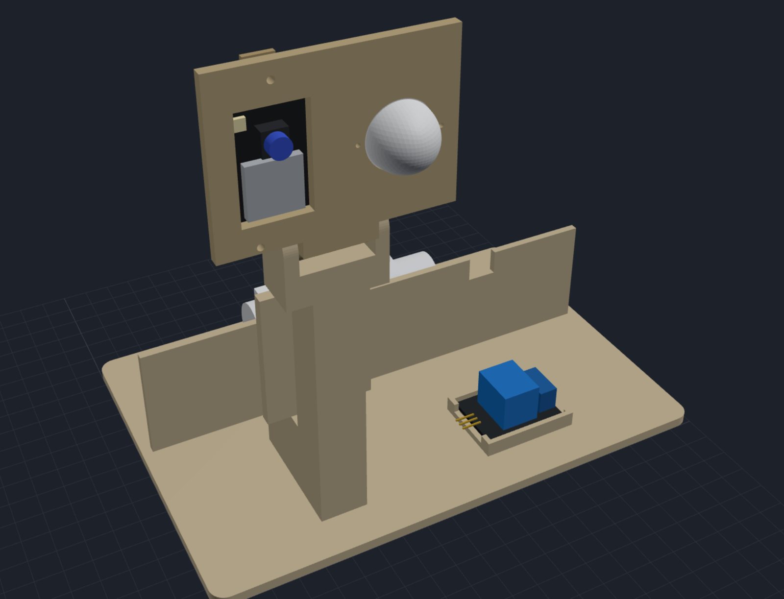
Result. The 12 V solenoid valve now opens and shuts on command. The ESP32-CAM drives the relay, the relay switches 12 V to the valve, and the valve clicks. No water through it yet. It's all mounted on the printed v2 test stand, which is now a kit of small parts on a pegboard-style base instead of one big print.
The circuit
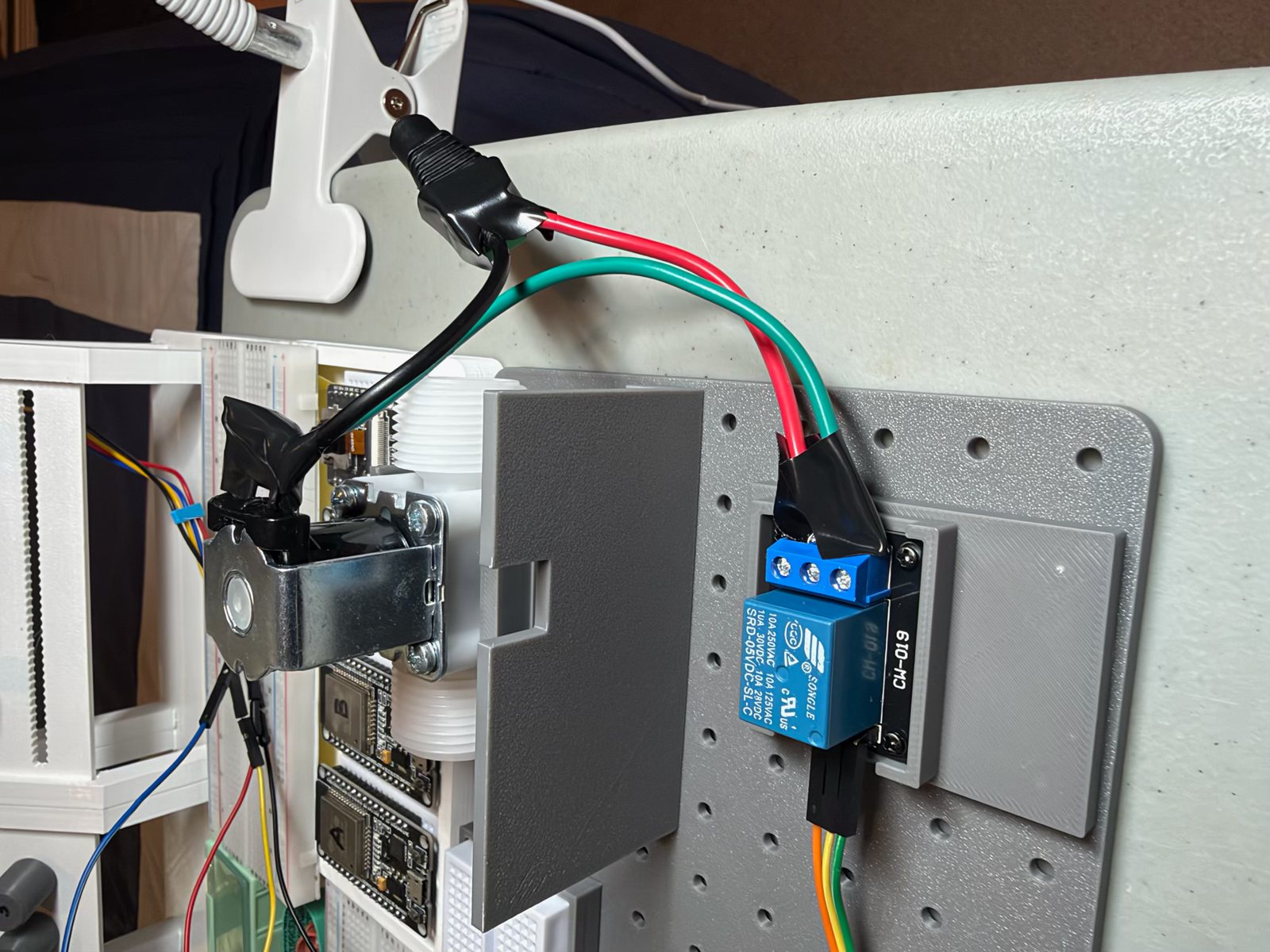
The relay is the wall between the two sides. The ESP32-CAM only ever sees the relay module's input: GPIO 13, about 2 mA. The relay's contacts switch the 12 V circuit, which never touches the camera's 5 V side.
| Side | Path |
|---|---|
| 5 V | rig hub 5 V → relay +, GND → relay −, CAM IO13 → relay S |
| 12 V | adapter + → relay COM; relay NO → valve; valve → adapter − |
| Spike catcher | a 1N4007 diode across the valve's terminals, band toward + (under the tape) |
The diode is there because a coil fights being switched off. When the relay opens, the valve's coil tries to keep its current flowing and throws a voltage spike. The diode gives that current a short loop back through the coil instead of arcing across the relay's contacts.
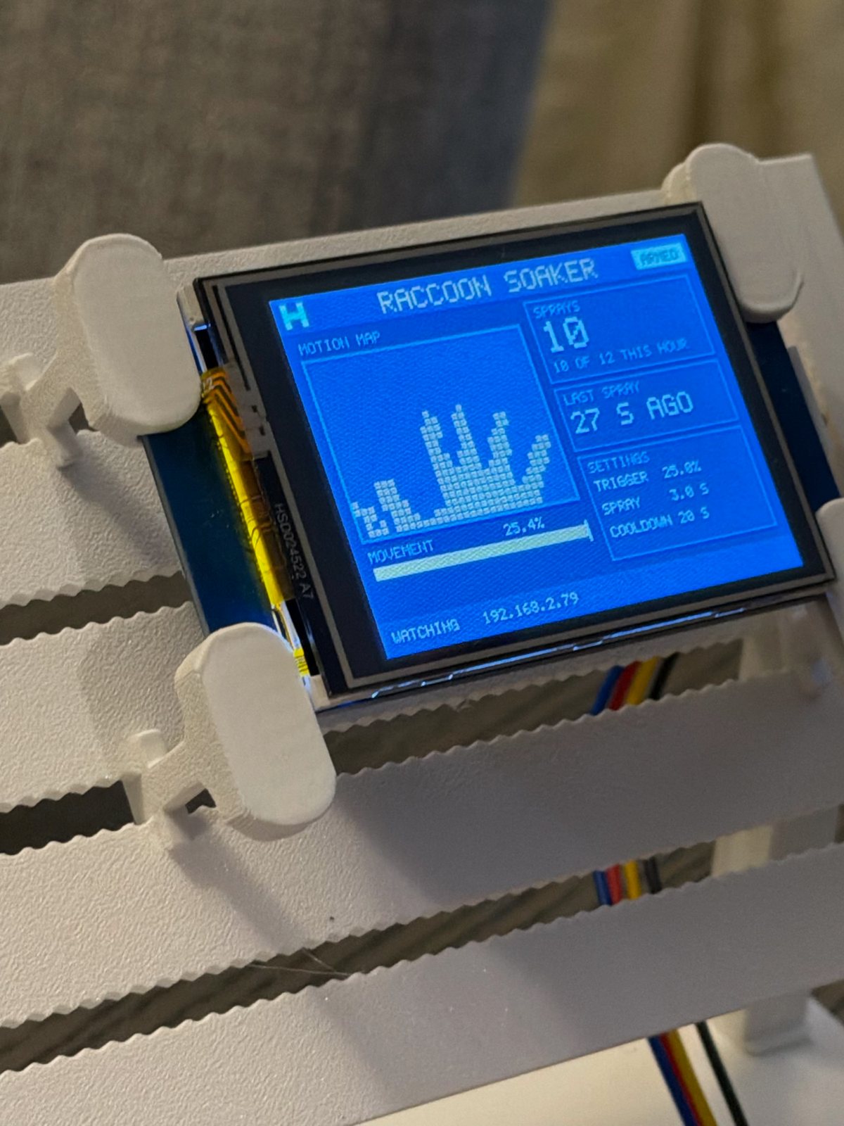
Wired one stage at a time on the rig (power first, metered at about 5 V, then the display, then the relay), the relay worked first time. Press Spray now in the phone app and you get two clicks: the relay, then the valve.
Measuring before printing
My first models used guesses for the valve. When I measured it, it was 73.66 mm long, 34.75 mm wide and 56.67 mm tall, with threads of about 26 mm. That's shorter than the 90 mm I'd assumed. Putting the real numbers into the model exposed a mistake the guess had hidden: the clamps sat on the threads, exactly where the hose fittings screw on, leaving about 2 mm free.
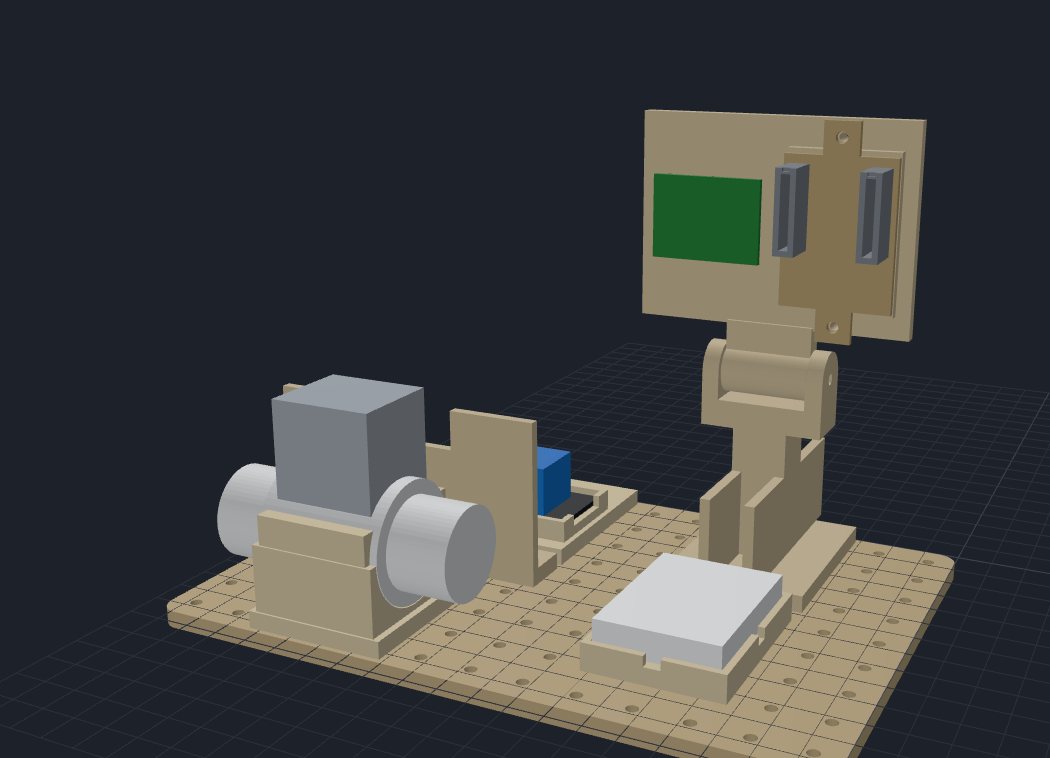
So the cradle now holds the valve by its body. There's a saddle under the wide middle, and both threads stand clear with about 18 mm free at each end. The script checks that a ¾" hose nut fits on each one. In the print I lowered the walls to 33 mm and dropped the strap: on the stand the valve just sits in the saddle.
A kit, not a print
v1 of the stand was one big print, and every mistake meant reprinting all of it. v2 is a base plate with M3 holes on a 15 mm grid, with every precision piece as its own small print screwed on from underneath: the camera head and its hinge, the relay tray, the valve cradle, the hub breadboard's tray. The model script checks that every module's screw holes land on the base's grid, so they can be moved around too.
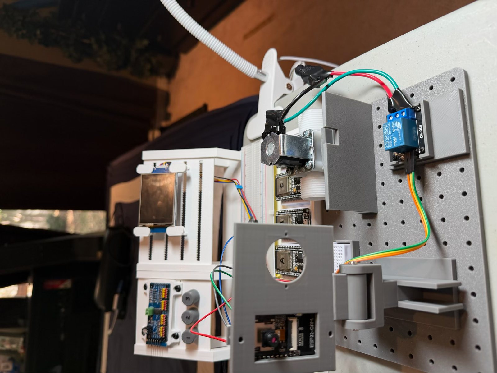
In this print, the relay's pocket is 1 mm bigger than v1's, with posts for its four screws. Changes in the model since, still to print:
- The hub breadboard's tray shrank to the board itself, with notches for its joining nub.
- Two small jumper guides clip into the camera cover's pin slots and keep the row of plugs in line.
What's next
Water. A hose on the inlet, a short run into a bucket, and Spray now: does the valve open fully on 12 V, and how far does it throw? After that, the coil's real resistance and current (I'm still using a typical 28 Ω, about 0.43 A), and a printed nozzle.
What I learned
- Measure before you model, or at least before you print. The guessed valve fit the guessed cradle perfectly. The real one showed the clamps were in the wrong place.
- A relay is a wall. The 3.3 V pin and the 12 V coil never meet: a couple of milliamps on one side switches nearly half an amp on the other.
- Every coil needs a diode. It costs a few cents and saves the relay's contacts.
- Wire in stages. Power, then display, then relay, checking each. Nothing to debug when it works first time.
Comments (0)