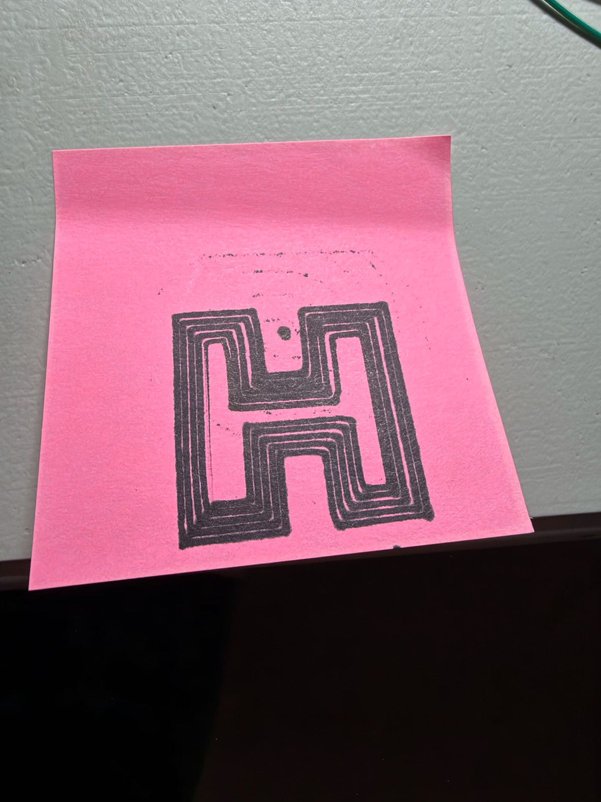
Result. The pen plotter is built, wired and drawing. Its first picture is a "hypnotic H" for Hypnochip: the H's outline in five rings 1.3 mm apart, one continuous line, about 100 seconds. All five rings came out closed and in the right shape. It also showed me the next things to fix: backlash on X, ink bleed, and a pen that touches down when it shouldn't.
The machine
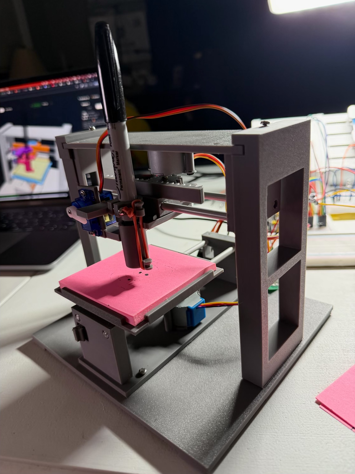
Version A reuses the test axis from milestone 2. It's turned upside down on two legs as the X axis (the pen moves left and right), and a second test axis lies front to back underneath as the Y axis (the pad moves in and out). Everything except the motors, needles, servo and screws is printed on the P1S.
| Part | Details |
|---|---|
| X axis | the test axis, flipped; the pen holder screws under its carriage |
| Y axis | a second test axis; the tray for the post-it pad screws onto its carriage |
| Motors | two 28BYJ-48 on ULN2003s: X on PCA9685 channels 12–15, Y on 8–11; 4096 half-steps per turn, 69.92 mm per turn |
| Pen | Sharpie Fine Point in an 11 mm tube; a collar clamped on its 11.98 mm body |
| Pen lift | SG90 on GPIO 13 (its own pin: the PCA9685 runs at 1500 Hz for the steppers); a rubber band pulls the pen down, the servo's horn lifts it |
| Power | adapter 7 V → MB102 → 5.0 V rails for both ULN2003s and the SG90 |
Measurements
| What | Reading |
|---|---|
| Pen up / down pulses (saved on the board) | 1530 / 1150 µs (I'd noted 1550 / 1000 from the first try) |
| +X half-steps | the pen moves to my right |
| +Y half-steps | the pad moves away from me (so the pen moves down the page) |
| SG90 horn: tab face to the arm's front face | 15.42 mm |
| SG90 horn: shaft to tip | 16.12 mm |
| Pen lift with a full pad | 5.4 mm (horn −60° down, +20° up) |
| First drawing | 40 × 40 mm, 983 mm of line, ~100 s |
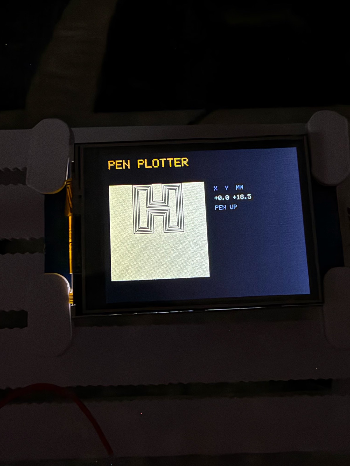
While it plots, the Nextion draws each line as the pen finishes it, on a picture of the pad at 2 pixels per mm, with the position and pen state beside it (after the Hypnochip splash). The screen shows what the plotter was told to draw: crisp, evenly spaced rings. Comparing it with the paper separates the machine's errors (backlash, bleed) from the drawing's. The top of the H runs off the screen's pad because of the 18.5 mm shift. The screen assumes the pad is centred under the pen, which will be true on the new baseboard.
What went wrong on the way
- The first frame snapped while I was taking the supports off. One post of each leg was only 1.5 mm thick, and the legs printed standing up, so they were weakest along their layers. The new legs print lying down, with 7–8 mm posts and no supports, and screw to a separate baseboard.
- The collar's tab was 15 mm short of the servo horn. The servo's shaft and hub stick out further than the model had drawn. Measuring the real horn (15.42 and 16.12 mm) fixed it.
- The pen couldn't reach the top of the pad. The pen hangs 31.5 mm in front of the X carriage, but the Y axis was centred under the X axis instead of under the pen. To get the pad under the pen I'd pushed the Y carriage most of the way forward, which leaves only ~13 mm of travel. The 3D view showed it: the real pad sat further forward than the drawn one. A new baseboard moves the Y axis 31.5 mm forward. Until it's printed, I zero with both carriages centred on their rails and shift drawings 18.5 mm up the pad.
What the first plot shows
- Backlash on X. The left leg's rings merged into a solid band while the right leg's spread out. That's what happens when an axis loses about 1 mm every time it reverses: everything drawn after a reversal lands slightly off. We measured only 0.01 mm on the bare test axis, so something in the build has play (the pinion on its shaft, the rack mesh, the tray, or the pen rocking in its tube).
- Ink bleed. A Fine Point Sharpie on post-it paper spreads to about 1.5 mm, so rings 1.3 mm apart nearly touch.
- Dots where the pen should be up. There's a dotted outline above the H, probably from an earlier Square run with the pen just touching, plus a dot where the pen first went down.
What I learned
- Check that the machine can reach its work area, not just that nothing collides. Every check passed and the pen still couldn't reach a third of the pad.
- Check strength as well as fit. A part can pass every collision check and still be too thin to survive having its supports removed.
- Measure the real part. The datasheet servo and the one on my desk differ by 6.5 mm where it matters.
- Know which way is "right". Facing the plotter, the 3D model's +x is on my left. The firmware uses my left and right, and the 3D view now does too.
- A plot is a measurement. Squeezed rings on one side and spread rings on the other point straight at backlash, and tell you which axis.
Comments (0)