The PD trigger board is 23 by 11.8 mm and weighs almost nothing, and the first holder I printed for it still let it move every time I touched the cable. The board sat on a small sled with barely any grip, and a USB-C plug going in is a push against the one part that has to stay put.
The board is the little module that asks the power bank for 9 V. It has no mounting holes, so a holder can only hold the edges. Its USB-C receptacle sits flush with one end, 9.38 mm wide and 3.57 mm tall, and the whole board has to line up with a 16 by 12 mm opening in the pod's wall, 58.6 mm above the floor, where the bank's cable arrives. Nothing about it is forgiving.
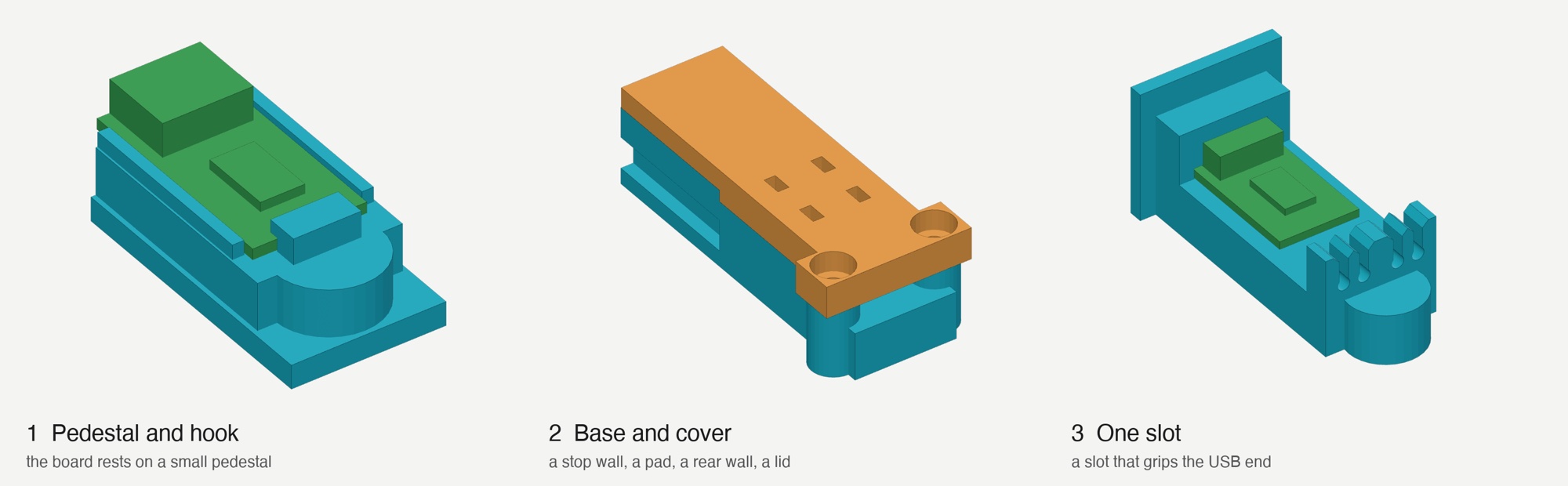
Try one: a pedestal with a hook. The board rested on a pedestal, two low ribs kept it from sliding sideways, and a hook at the far end held it down. It worked on the bench and failed the moment a plug went in. The only thing resisting the push was friction.
Try two: a base and a cover. The base got a stop wall at the far end, so a plug pushes the board against plastic. The cover pressed a pad onto the receptacle's shell and had a rear wall just behind it. It held better, but it was two parts to print, fit and screw down, and I didn't like it. I told the model what I wanted instead: one part, with the slot doing the gripping.
Try three: one slot. A front plate sits on the wall's inside face and covers the whole 16 by 12 opening, with a rounded hole just big enough for the plug (11.74 by 4.13 mm measured, plus 0.5). Behind the plate is a T-shaped slot, 5 mm deep, shaped to the board's cross-section: the board's width low down, the receptacle's shell above it. You lower the board in behind the slot and push it 5 mm forward. The board's end face then bears directly on the back of the front plate, so a plug going in pushes the board into plastic. A pull is held by the slot's grip. Behind the slot there's a floor and a short comb wall with four wire bores, so the output wires have somewhere to go before they reach the board's pads.
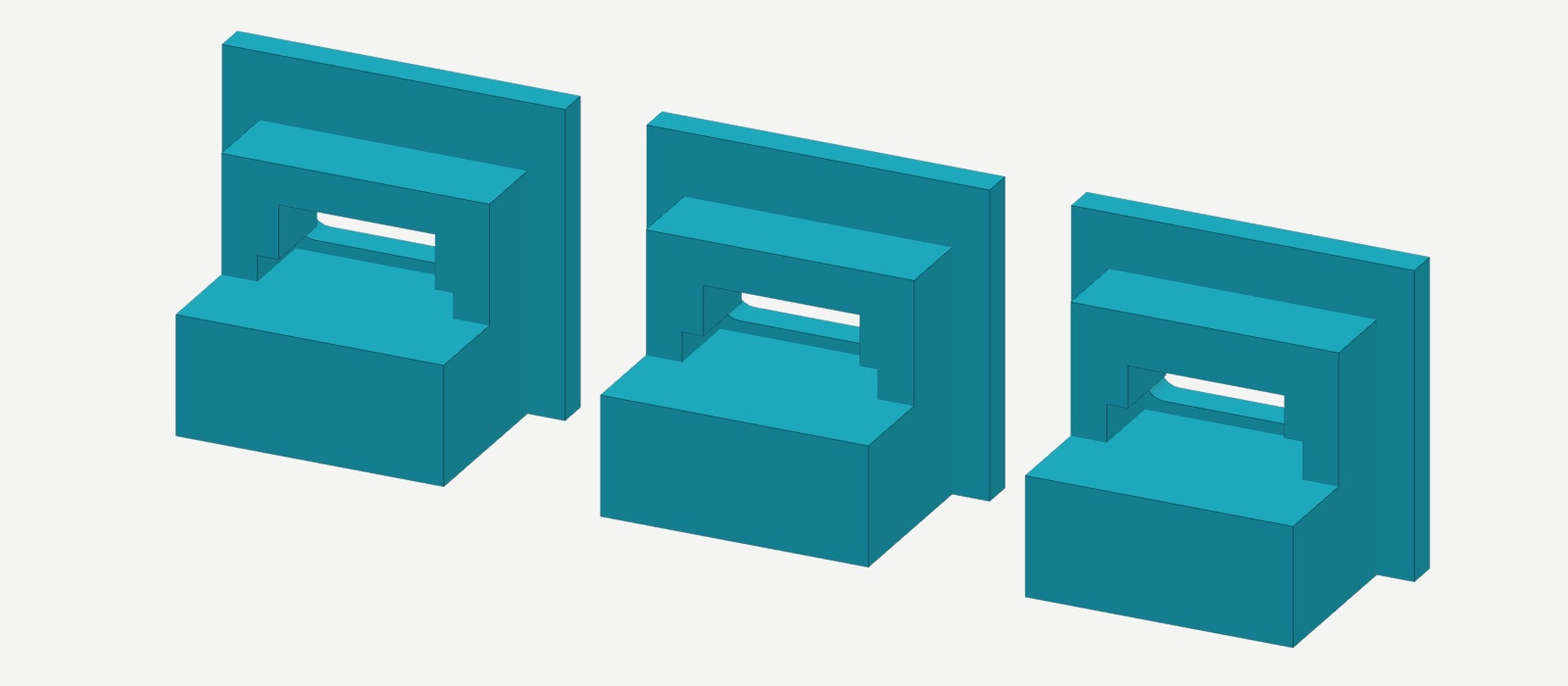
I didn't trust the slot's size, so I printed coupons: three short copies of the slot, one dimple each to say which is which. The first round was the board's width and height at three clearances, and the board was too tight vertically in every one. The second round left the sides alone and raised the ceiling by 0.25, 0.50 and 1.00 mm. Result: one dimple, the 0.25, fits best. That's the number in the model now.
One thing still worries me. The plug's overmold has a lower edge 0.28 mm below the top of the board, so a real plug may stop against the board's end instead of travelling the last 0.7 mm to the mouth. The coupon was tested with the board, not with the plug in it. Before I print the module for the pod, the real plug goes into the real slot first.
Comments (0)