Version 4 of the soaker's enclosure is printed, assembled and wired. The camera, the mini PIR, the relay and the valve all work inside the real box. Along the way, the PIR bezel didn't fit the PIR, the valve got no power, and the camera turned out to be blind in the dark. Each one has a fix. Next are the rail mount and the yoke, so it can go on the deck.
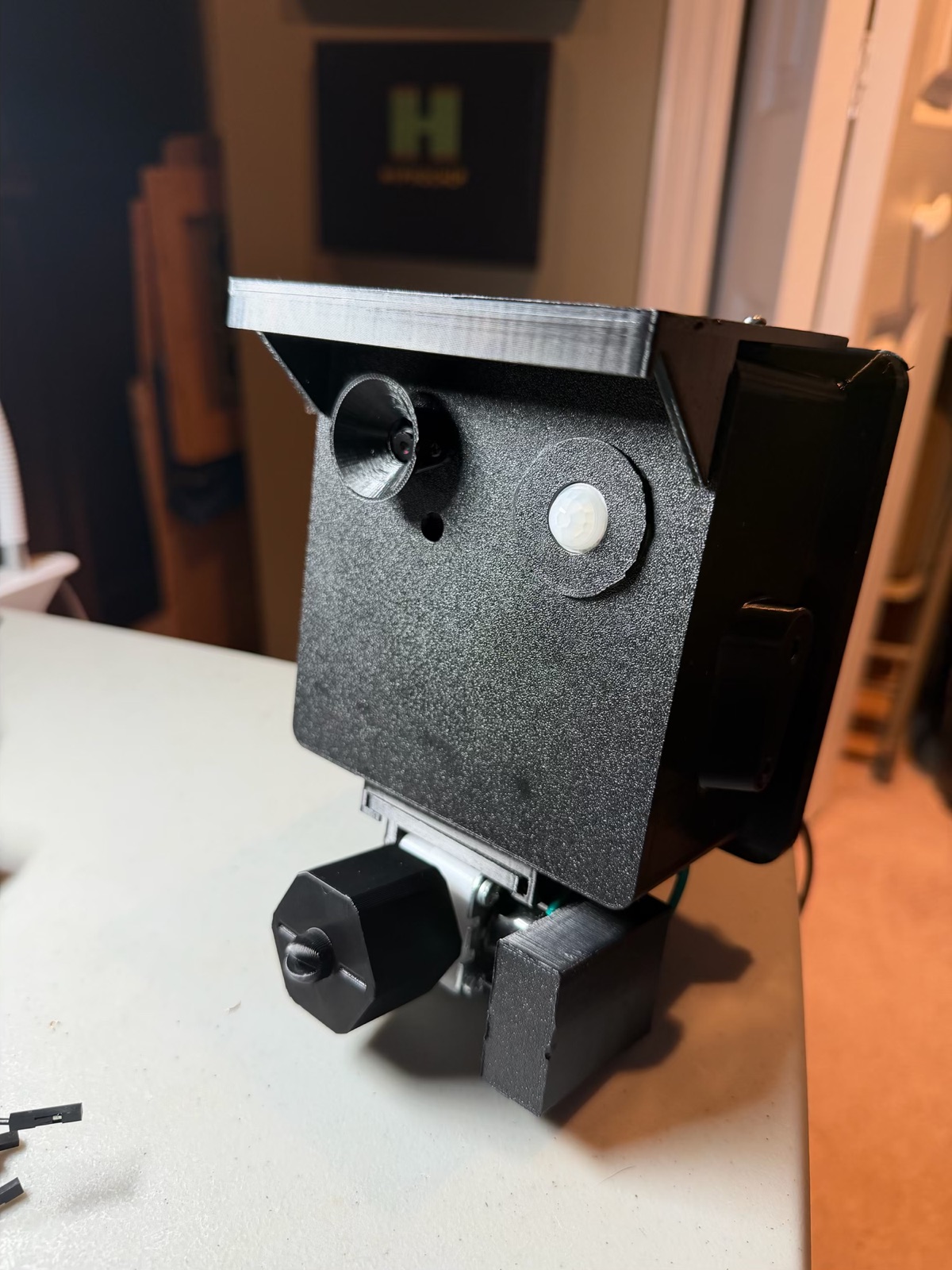
Printed and assembled
From part 4, these are all printed now:
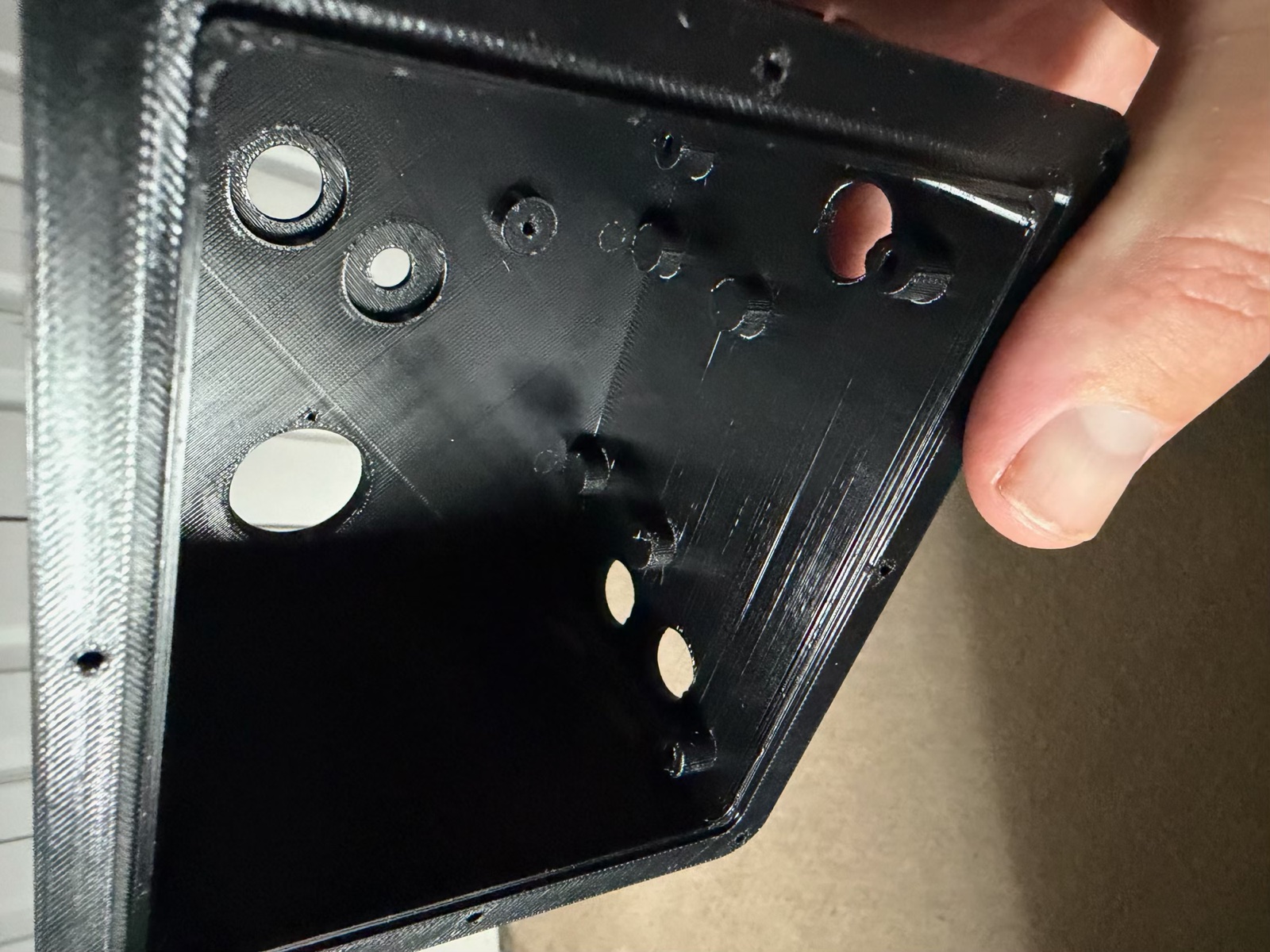
- the box body, the biggest print
- the sled and its two brackets
- the camera carrier and cover, and the lens hood
- the rain hood and the PIR bezel
- the valve's hanger and bracket, and the terminal boot
- the nozzle
The sled feels really good. I build everything on it at the bench, slide it in from the back, and put in two screws at the opening.
The 60° fan nozzle twisted onto the valve's outlet perfectly on the first try. After the valve took a whole post of measuring, that was a nice surprise.
Holding it assembled, I wanted one more part: a small brace from the top of the camera cover across to the side wall, so the camera can't rock. It hangs on the cover's top screw through a 4 mm slot, so I can wedge it against the wall before tightening.
The wiring
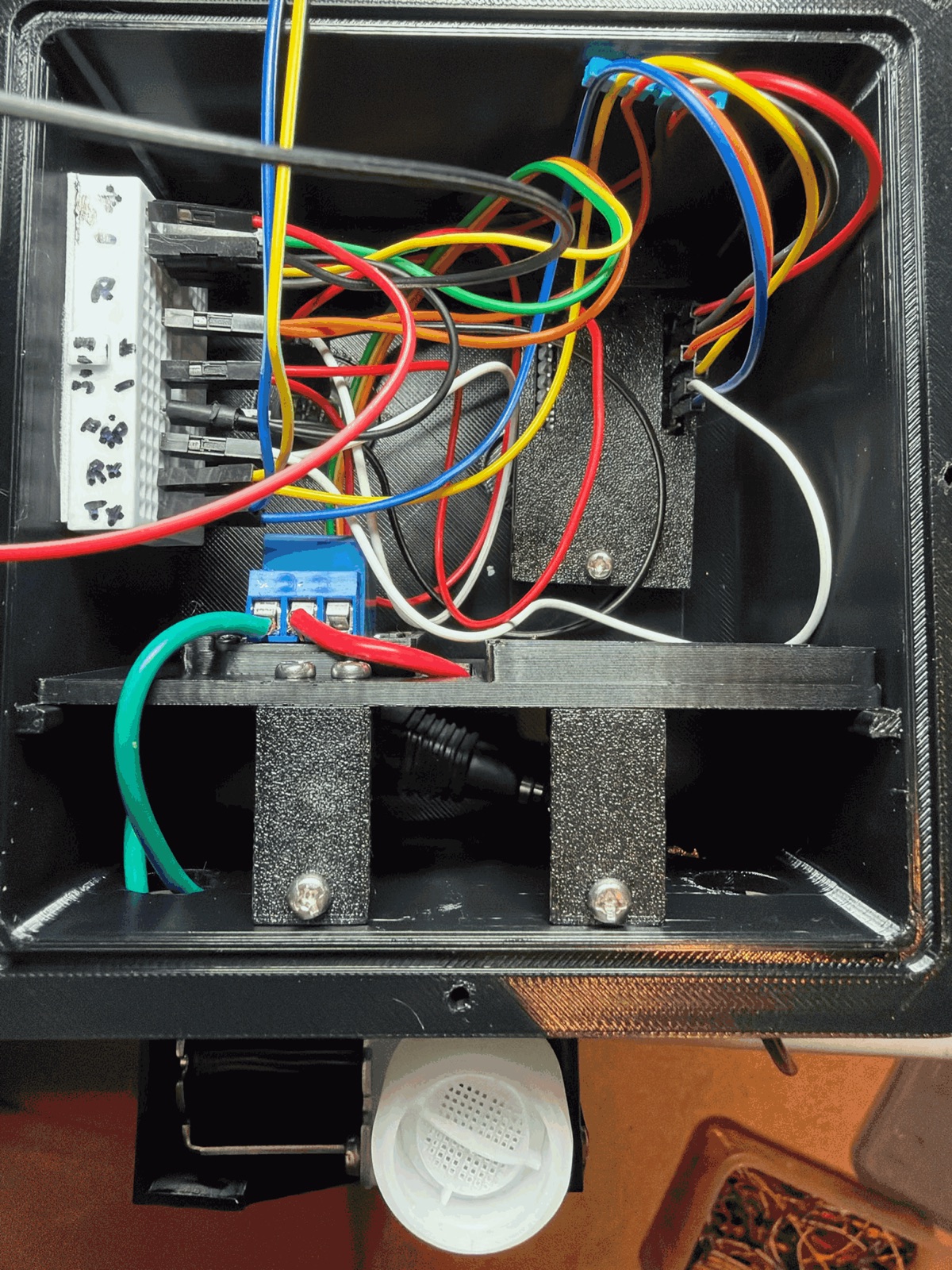
The camera, the relay, the buck converter and the PIR all have to meet somewhere. I glued a 170-pin mini breadboard to the inside of the left wall and ran jumpers to it. It's not pretty, but every connection can still be changed, and that matters while things are still being tested. The relay's 12 V side is on its blue screw terminal.
Under the sled you can see the cable basement from part 4 earning its keep. The power cable and the valve's wires come up through their glands and bend under the sled instead of pushing into it.
The relay clicked, but no water
With everything wired, Spray now clicked the relay, but the valve did nothing. The meter read nothing across the valve's terminals while it was spraying.
The way to find it was to trace the 12 V from the adapter to the valve one point at a time. I kept the black probe on the 12 V minus and touched each of these:
| Point | At rest | Spraying |
|---|---|---|
| Relay COM | 12 V | 12 V |
| Relay NO | 0 V | 12 V |
| Valve, + side | 0 V | 12 V |
| Valve, − side | 0 V | 0 V |
The first point that reads wrong is where the fault is. Mine was simple: a wire had come loose on the DC jack. The relay was switching, just with no 12 V to switch.
The PIR bezel didn't fit
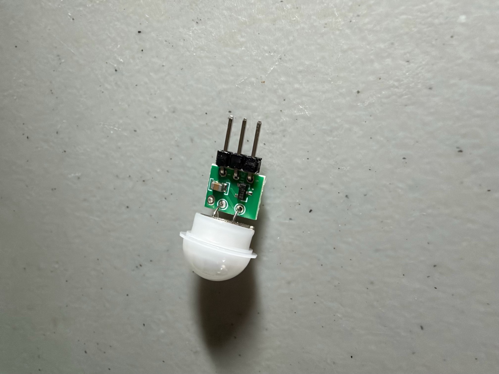
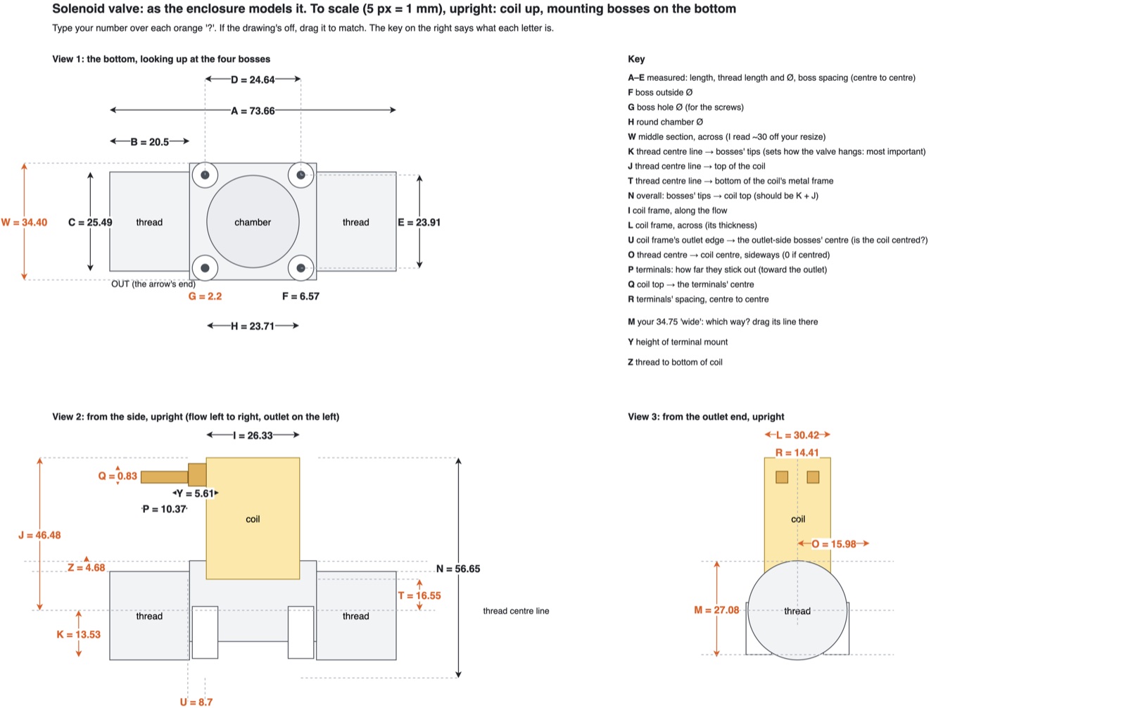
Part 4 ended with a question: did the AM312's dome have a rim that the listing didn't show? It did, and the PIR didn't fit the bezel. I'd printed the bezel from the listing's sizes. When I measured the real sensor on a drawing with a letter for each dimension, as I did for the valve:
- the rim is 13.95 mm across, and the bezel's bore was 12.4
- the can behind the dome is 10.64–10.89 mm, and the bore behind the shoulder was 10.6
The rim wouldn't go into the bore, and the can wouldn't go through it. For now the PIR is super-glued into the first bezel, and it works. The redesigned bezel has a shallow counterbore in its face for the rim and one straight 11.4 mm bore behind it. It's ready to print when this one needs replacing.
Blind in the dark
The PIR sees movement on GPIO 14 and shows it in the phone app. The first test in low light found a gap: in low light the PIR saw movement, but the camera didn't see enough to fire, so nothing sprayed. That's the opposite of what I want, because raccoons come at night.
So "Spray when" has a new setting, auto:
| Light | Sprays when |
|---|---|
| Daylight | the camera and the PIR agree: fewer false sprays from shadows and wind |
| Dark | the PIR alone: the camera can't see |
The camera measures the light itself: the average brightness of its picture, 0 to 255. The app shows it, and the dark threshold is a setting. I'll set it from what it reads on the deck at dusk. That also means I probably don't need the photoresistor I'd planned for day and night.
I tested it in Bench's Preview first. With the camera's trigger set too high to fire, the stand-in raccoon set off a spray in the dark through the PIR alone, and not in daylight.
I haven't added the 100 nF capacitor across the PIR yet. It's there to stop the ESP32's Wi-Fi from tripping the PIR. The app counts the PIR's triggers, so a night with nobody around will show whether it needs one.
Smaller things
- Catches open full size. Tapping a catch or a snapshot in the app now opens it full width, and you can swipe through the rest.
- Wi-Fi updates. Every firmware change in this post, including auto, went onto the board over Wi-Fi.
What's next
- The rail mount and the yoke: the saddle that sits on the deck rail, the yoke that pans on it, and the ears the box tilts on. They need more room for their nuts, so I'm redesigning them before printing.
- Then water through the valve, the dusk light reading, and a night on the deck.
What I learned
- Measure the part, not the listing. The valve taught me that and the PIR taught me again. A drawing with a letter on each dimension makes it quick.
- Trace power one point at a time. "It clicks but nothing happens" is a missing voltage somewhere along the path, and a meter finds it in a few minutes.
- A camera can't be the only sensor at night. The PIR isn't just a second opinion: after dark it's the only one that can see.
- Keep wiring changeable until it's proven. A breadboard glued inside the box isn't the final answer, but it's the right one for now.
Comments (0)