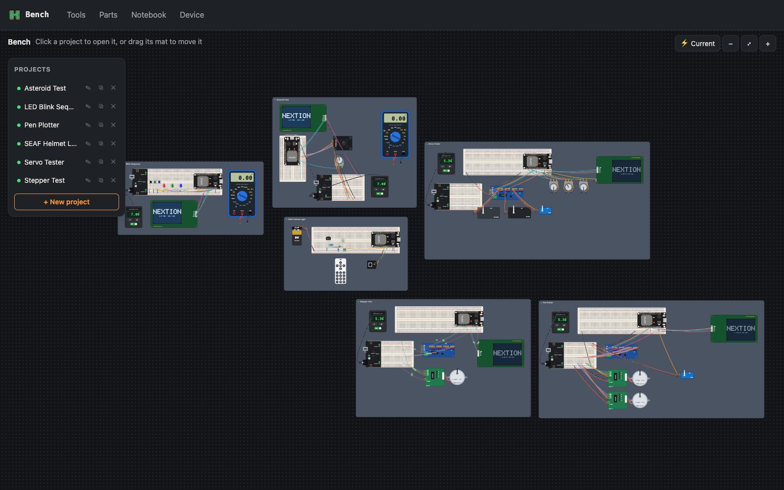
Result. The Pen Plotter on Bench's canvas is now laid out the way it's really built on my studio rig, with every wire going through the same little "hub" breadboard as the real thing. The circuit came out provably identical. Two new tools came out of it: Tidy wires, which untangles jumpers without changing anything electrical, and Arrange to rig, which lays any project out like the rig. One of them still has a rough edge.
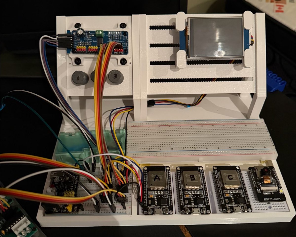
The rig, as it really is
The canvas had drifted from my desk. The real setup, seen from the front:
- Panel: the PCA9685 servo driver top left, three potentiometers (knobs 1, 2, 3) under it, the Nextion display on the right.
- Base, back: a long 830 breadboard, empty for now.
- Base, front left: a 400 breadboard with the MB102 power module on its end. This is the hub: every connection is staged here, even the Nextion's jumpers, so all the wiring meets in one place.
- Base, front right: a dock of mini breadboards, one per board: ESP32s labelled A, B and C, then an ESP32-CAM. On the DevKits only the left row of pins is reachable; the CAM is narrower, so it sits centred and both rows are free.
The labels matter: a project can now say "this runs on A".
Rebuilding the Pen Plotter on it
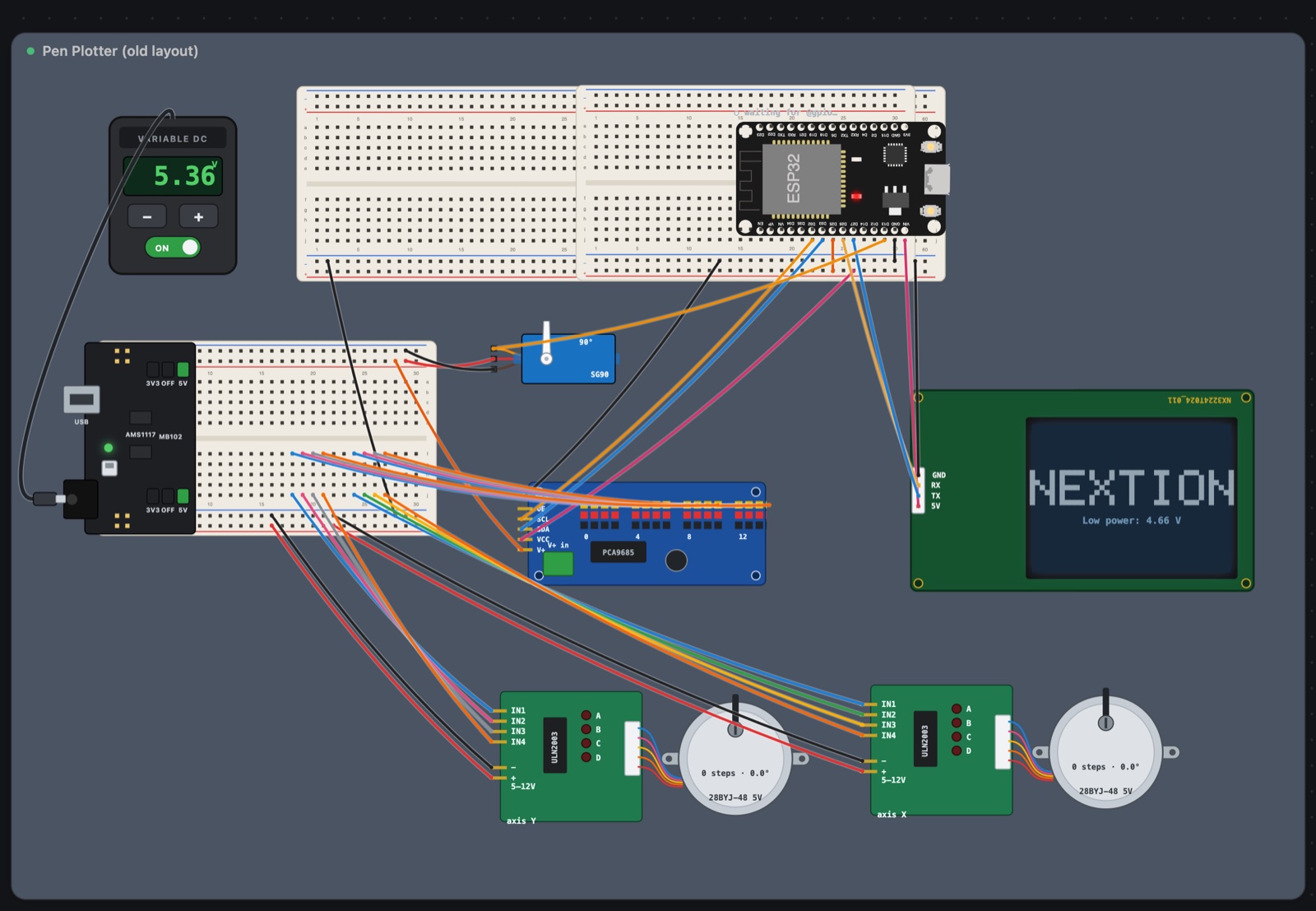
I rebuilt the Pen Plotter project to match: the PCA9685 and Nextion on the panel, ESP32 A on its own mini breadboard in the dock, the hub with the MB102, and each of A's signals (I2C, the display, the pen servo, power) given its own column on the hub, with the modules plugging into the same columns.
| Before (the old loose layout) | After (the rig) |
|---|---|
 |
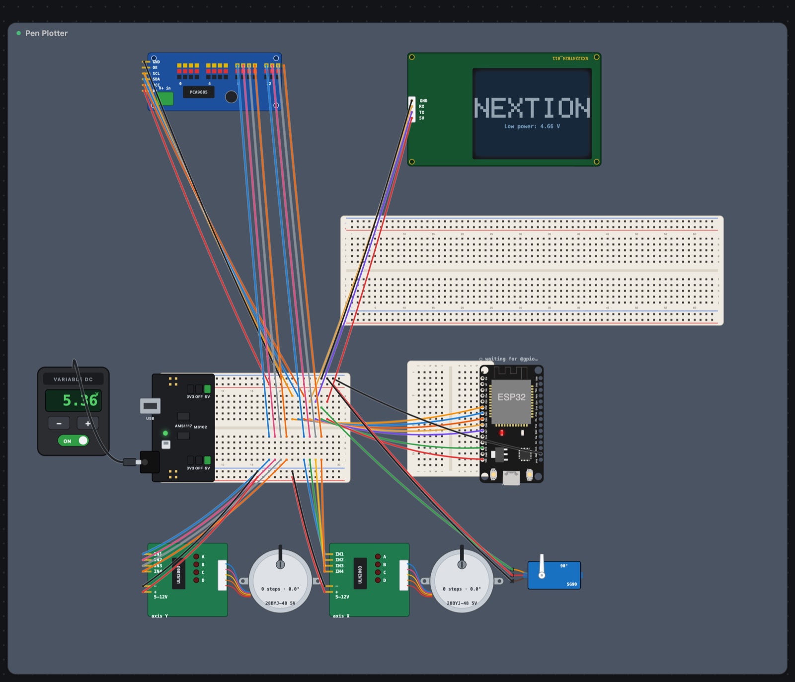 |
Moving everything around is the easy way to break a circuit without noticing. So Bench checks: it lists every connection as the set of part pins it joins, before and after. All 18 matched exactly. The old layout went into a new, hidden Archive group rather than being deleted.
Bench also needed a part it didn't have: the 170 mini breadboard (17 columns, no power rails) the ESP32s sit on.
Tidy wires
Crossing jumpers make a canvas hard to read and a real build hard to check. But you can't just move parts around to fix it: the canvas is supposed to match the desk.
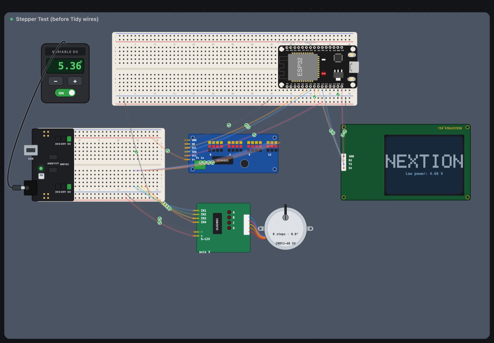
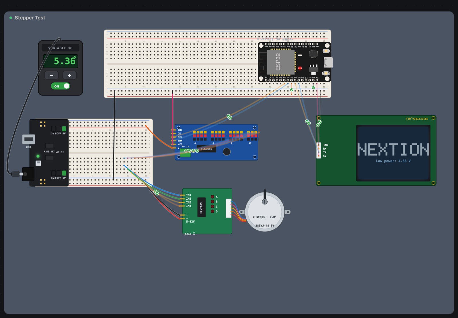
The trick: every hole in a breadboard strip (the five holes of a–e in one column) is the same connection, and so is every hole along a power rail. So a jumper's end can move to any free hole in its own strip without changing the circuit at all. Tidy wires tries those moves for every jumper end and keeps the arrangement with the fewest crossings, then the shortest wire. Parts never move.
| Stepper Test, before | After Tidy wires |
|---|---|
 |
 |
| Project | Crossings before | After |
|---|---|---|
| Core Alpha | 72 | 43 |
| Servo Tester | 28 | 17 |
| Stepper Test | 17 | 6 |
| Asteroid Test | 13 | 10 |
| SEAF Helmet Light | 4 | 1 |
| LED Blink Sequence | 3 | 1 |
Every one came out with the circuit identical. I ran it on the projects that aren't wired up right now, and not on the Pen Plotter: its canvas matches the jumpers actually plugged in on my desk, and I don't want the two to disagree.
Arrange to rig, and its rough edge
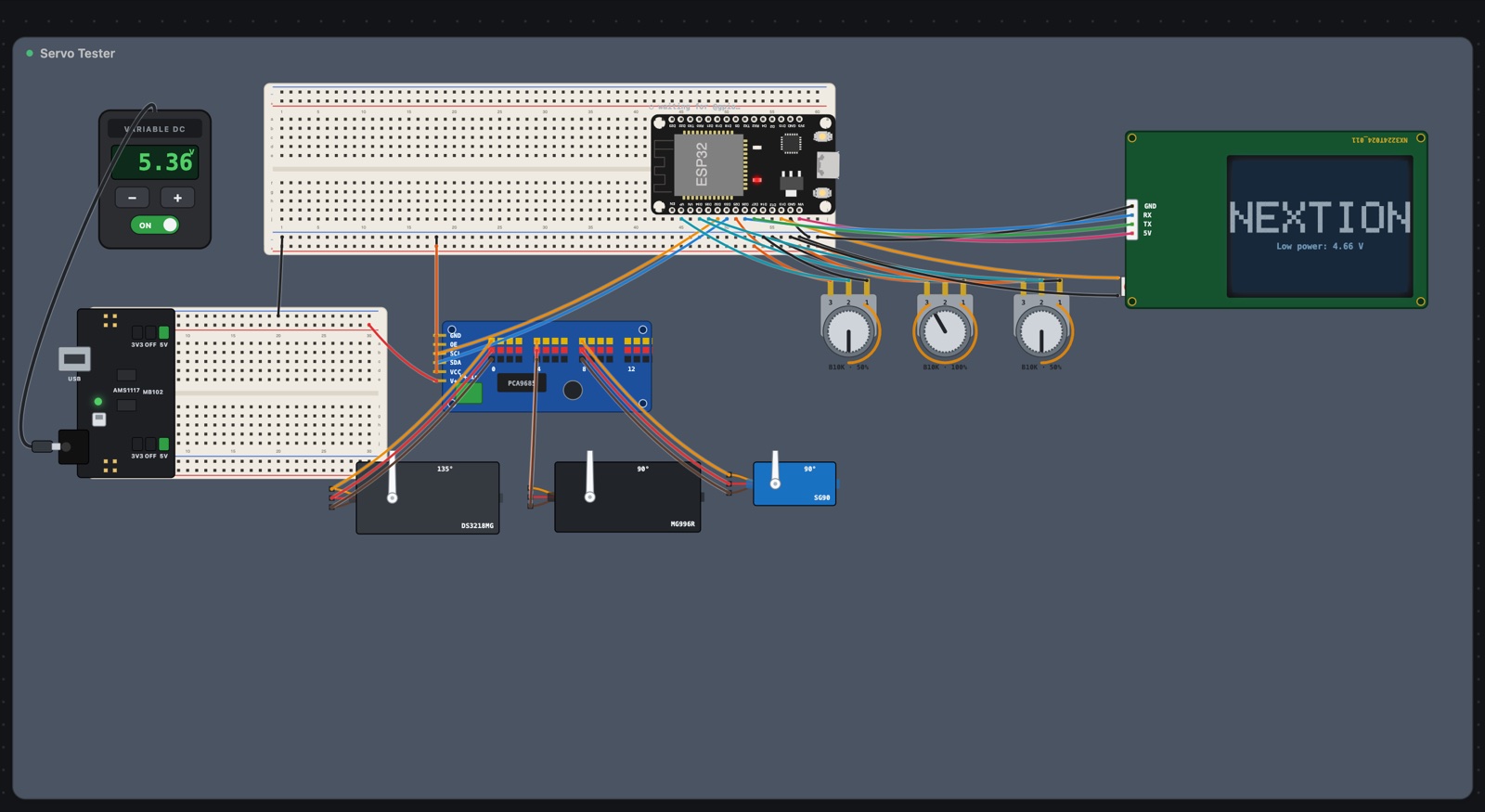
Then the obvious next step: do the Pen Plotter treatment to any project, automatically. Arrange to rig puts the panel parts on the panel, the ESP32 in the dock slot you pick (A, B or C), the hub front left, the breadboard the ESP32 was on at the back with everything still plugged into it, and motors, servos and the like out in front. Where a part leaves a breadboard, it adds a jumper back to the hole it left, so nothing gets disconnected. And again, if the connections don't come out identical, it refuses and changes nothing.
| Servo Tester, before | Arranged to the rig |
|---|---|
 |
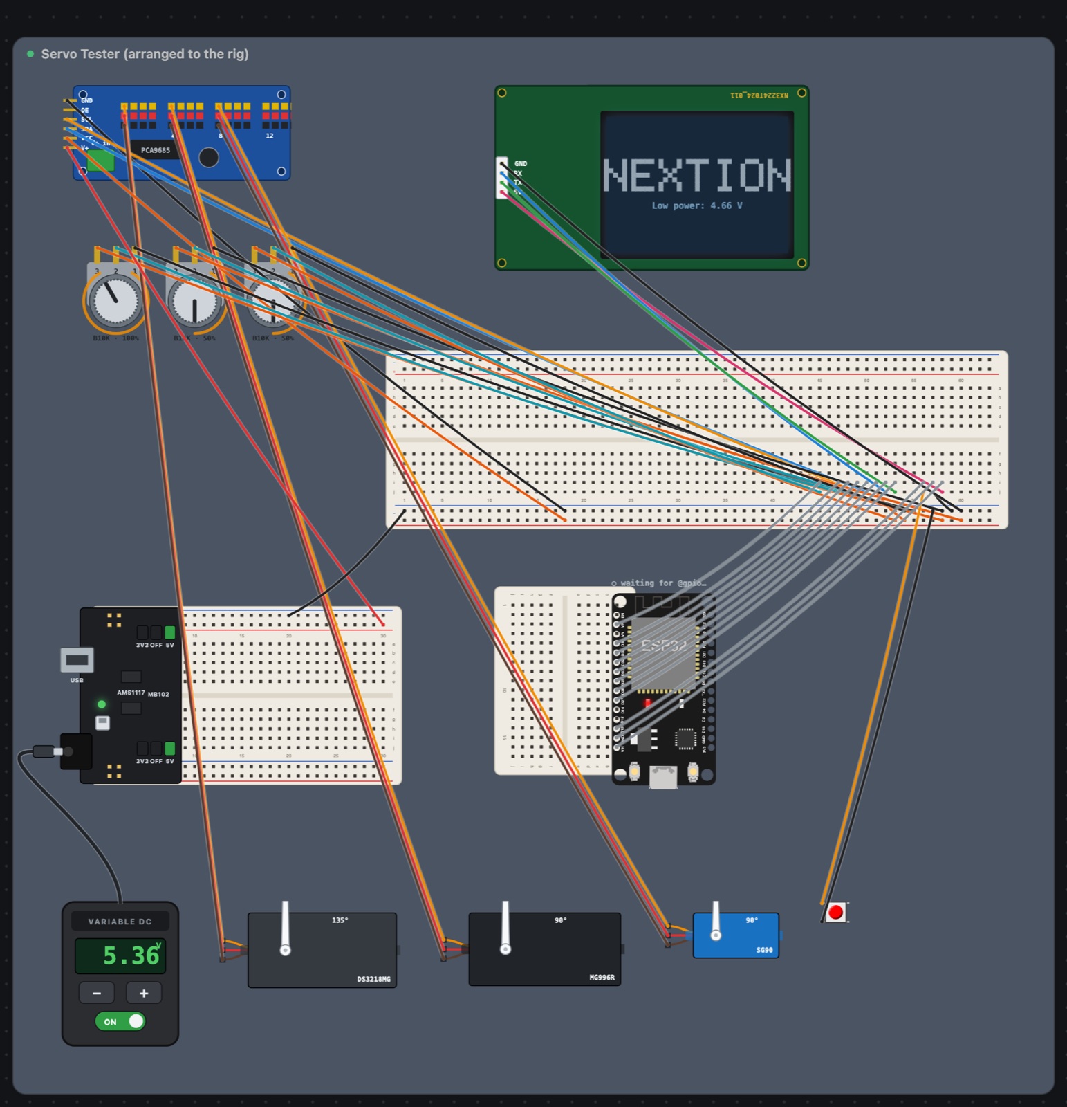 |
It works, and the circuit is identical, but look at the after picture: long jumpers run all the way back to the long breadboard, where the ESP32 used to be plugged in. That's faithful, but it isn't how I'd wire it. When I rebuilt the Pen Plotter by hand, I moved each connection onto the hub. The automatic version keeps every connection where it was. Teaching it to re-stage connections on the hub is the next step.
Two bugs turned up along the way:
- Asteroid Test's breadboard was turned on its side on the canvas, and the first version only handled boards lying flat. It now turns a sideways board flat, with everything on it, as one rigid group.
- In a 1400-pixel-wide window, the Show / Readings / Current buttons sat on top of the project's ⋯ menu button, so the menu (where these tools live) couldn't be opened. The top bar now measures those buttons and wraps underneath instead.
What I learned
- Make the canvas match the desk, then prove it. Comparing the circuit as sets of connected pins, before and after, turns "I think I didn't break it" into a yes or no.
- A breadboard strip is one wire. Any hole in it will do, and that freedom is enough to untangle most crossings without touching a part.
- Label the hardware. A, B and C stickers on the ESP32s made "which board runs what" a non-question.
- Faithful isn't the same as good. The automatic arrangement keeps every connection, but a person would re-route them through the hub. Correct first, then make it nice.
Comments (0)